TN LNG & POWER PROJECT – SEA WATER INTAKE & DISCHARGE SYSTEM

(This article explains about the details of Sea Water intake and discharge arrangement planned in the year 2001 for LNG TERMINAL & POWER PLANT at Ennore near Chennai in Tamilnadu, India)

DETAILS OF SEA WATER INTAKE AND DISCHARGE ARRANGMENT

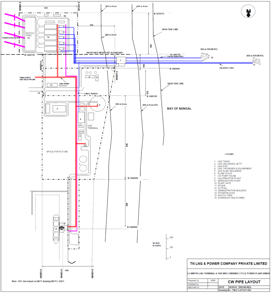
Seawater Circulating Water System

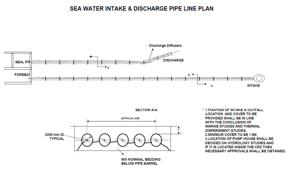
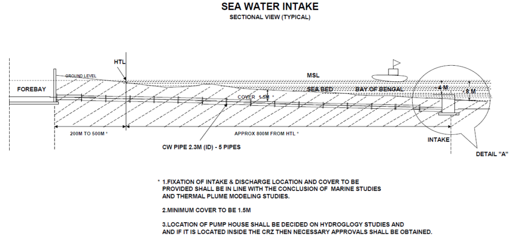
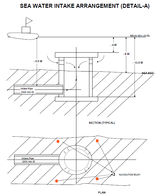
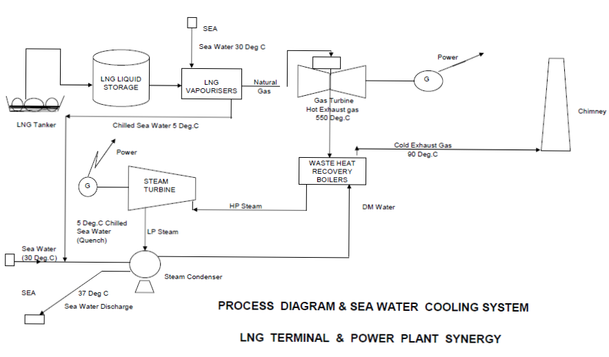
The seawater circulating water system releases condensing heat from the turbine condensing systems and the heat from the closed cooling water system to the ambient by means of sea water. Cooling water is taken out of the Bay of Bengal in the circulating water pump house and supplied by the circulating water pumps to the condensers and the service cooling water systems of the five units. A tube cleaning system and chemicals injection are provided to prevent fouling and mussel growth in the internal surfaces of the condenser.
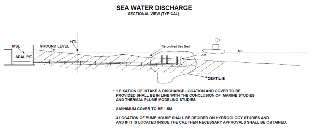
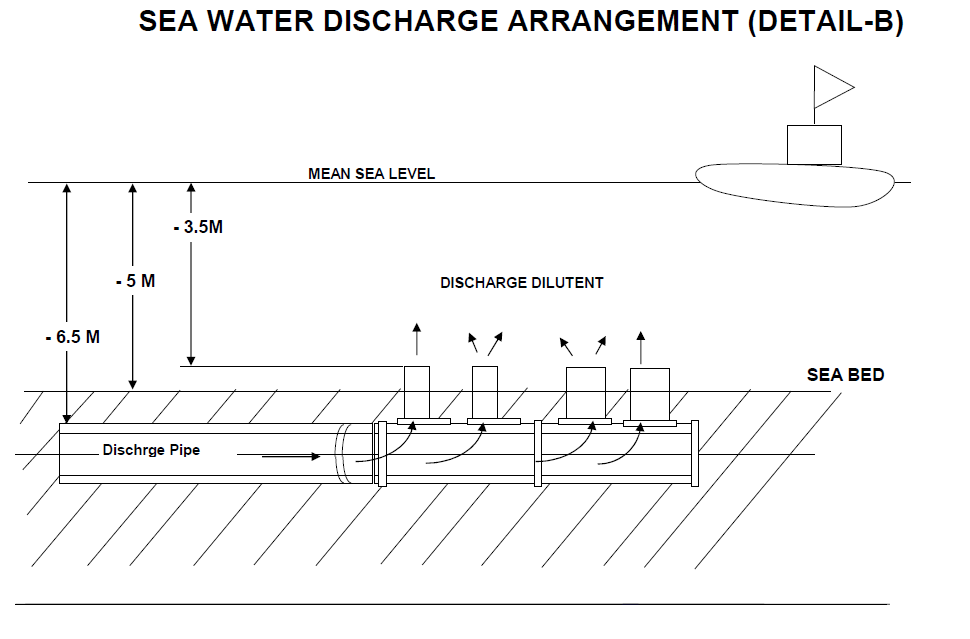
The circulating water system consists of five electric driven 20% capacity circulating water pumps that are designed for parallel service. The warmed up circulating seawater is pumped to the circulating seal water pit before release to the Bay of Bengal via the circulating discharge structure.  Certain amount of warmed up seawater will be diverted via regasification water pumps to the LNG Terminal for the use in seawater vaporizers. 

Circulating (Cooling) Water Intake Structure

Five intake structures are located in the Bay of Bengal about 800m offshore from the High Tide Line. The Pump House building is located 200 to 500 from High Tide Line onshore.
The intake structure will be made of reinforced concrete designed to withstand wave and current forces. They will be prefabricated onshore and placed connected to the inlet culverts by floating equipment. Scouring protection around the structure will be laid.

Cooling Water Inlet Culvert

Each intake structure will be connected by inlet culverts to the cooling water pump building. The length of each culvert is approximately 800m from High Tide Line.
Each inlet culvert is designed for a water flow of 7.62m3/s and constructed utilizing prefabricated concrete pipes with a diameter of 2300mm. The culverts will be laid and connected together by special offshore equipment under water in a dredged culvert trench.

Cooling Water Pump Building

The cooling water is taken from the intake structures through the intake culverts to the cooling water pump building where it will be channeled into five cleaning streets.
Each cleaning street contains one coarse screen and one traveling band screen for mechanical cleaning. The suction chambers for the main cooling water pumps are located behind the cleaning streets. Each cleaning street and its associated pump suction chamber can be closed by stop logs and emptied separately for maintenance purposes.
The construction shall be made of water-tight reinforced concrete. We have assumed a shallow foundation.

Cooling Water Seal Pit

The Cooling Water Seal Pit is located at Pump House building and is connecting the return cooling water pipes from the condenser with the cooling water discharge structure.

Circulating (Cooling) Water Discharge Structure

Five discharge structures are located in the Bay of Bengal about 500m offshore from the High Tide Line. The discharge structure along with diffuser will be made of reinforced concrete designed to withstand wave and current forces. They will be prefabricated onshore and placed connected to the discharge culverts by floating equipment. Scouring protection around the structure will be laid.

Cooling Water Discharge Culvert

Each discharge structure will be connected by discharge culverts to the seal pit in the cooling water pump building. The length of each culvert is approximately 500m from High Tide Line.
The culverts will be laid and connected together by special offshore equipment under water in a dredged culvert trench.
###

Leave a Comment

Your email address will not be published. Required fields are marked *